Technical Material
Specifications for AC Fan Sensor
ACDC fan sensor specifications differ from those below..
| 5 V (ITEM-20 (1)) | 12 V (ITEM-30 (1)) | |
| Example of model.no | 109S405UL | |
| System | Speed detection, Auto-restart, Open collector | |
| Power supply | 5 VDC±10% At 5 V, 6 mA | 12 VDC±20% At 12 V, 10 mA |
| Recommend sensor circuit output | At Vp= 5 V, I= 100 mA max. | At Vp= 12 V, I = 200 mA max. |
| Trip point | Standard speed: 1700 min-1±10% Low speed: 850 min-1±10% |
|
| Response speed | Standard speed: Startup delay 18 s Detection delay 1 s Low speed: Startup delay 36 s Detection delay 2 s |
|
| Insulation resistance | 10 MΩ min. at 500 VDC (2) | |
| Dielectric strength | 50/60 Hz, 1000 VAC, 1 minute (2) | |
| Ambient conditions | Temperature: -10 to +70˚C , humidity: 90% RH max. (at 40˚C) | |
 |
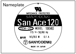
(1) [ITEM-20] and [ITEM-30] are printed on the fan nameplate. (2) Between lead wire conductors and frame |
Sensor output circuit
GND (Black) should be shared in case that power supply for sensor circuit (Brown) and that for sensor pull-up (Yellow) are separated.

* [ITEM-20] and [ITEM-30] are printed on the fan nameplate.
Sensor scheme
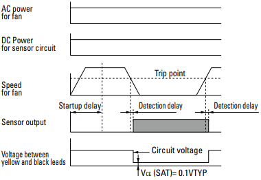
Example 1: When the AC power for the fan and the DC power for the sensor are turned on at the same time

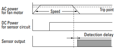
Example 2: When the AC power for the fan is turned on first, then the DC power for sensor is powered on

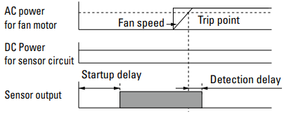
Example 3: When the DC power for sensor is first powered on, then the AC power for the fan is turned on

Last updated: November 2025


