Technical Material
Specifications for DC Fan Sensors
Pulse sensor outputs two pulse waves per revolution of fan, and it is good to detect fan speed. Pulse sensors can be incorporated in all kinds of DC fans.
Noise from inside the fan or from external devices may effect sensor output.
Specifications differ with models. Please contact us for details.
Output circuit: Open collector
Specifications
VCE=+30 Vmax.
IC=5 mA max. [VOL=VCE (SAT)=0.6 V or less]
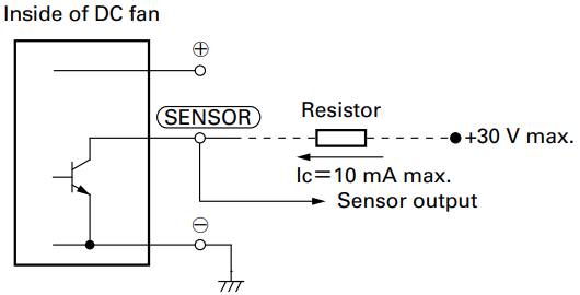
Output waveform (Need pull-up resistor)
In case of steady running
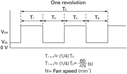
If you want detailed specifications that apply when the rotor is locked, please contact SANYO DENKI.
Locked rotor sensor outputs fan status signals. It is good to check whether the fan is running or locked
Noise from inside the fan or from external devices may effect sensor output.
Regarding details of the reverse logic and specifications of lock sensor output signals, please contact SANYO DENKI.
Lock sensor can not be used in some models. Contact us for more information.
Output circuit: Open collector
Specifications
VCE=+30 V max.
IC=5 mA max. [VOL=VCE (SAT)=0.6 V or less]
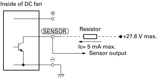
Output waveform (Need pull-up resistor)
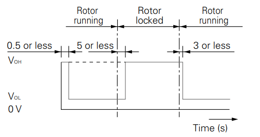
The output is completely at Vol with 0.5 s or less after power-up.
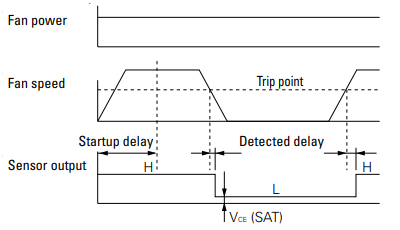
Low-speed sensor outputs a signal when fan speed goes down to trip point or less. It is good to detect cooling degradation of fan.
Noise from inside the fan or from external devices may effect sensor output, please.
If you want detailed specification and reverse signal output,please contact SANYO DENKI.
Low-speed sensors can not be used in some models. Contact us for more information.
Output circuit: Open collector
Specifications
VCE=+27.6 V max.
IC=10 mA max. [VOL=VCE (SAT)=0.5 V or less]
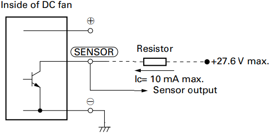
Sensor scheme
Example 1: In case steady running
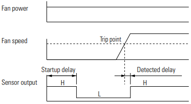
Example 2: In case that the rotor is locked when the fan motor is turned on and released after the start-up delay time
Last updated: November 2025


