Technical Material
Fans with PWM Control
1. Overview
Pulse Width Modulation (PWM) control enables you to externally control the speed of the fan by varying the duty cycles of PWM input signals between control and grounding terminals.
It allows fans to operate optimally in response to the device's heat level, lowering the noise and power consumption of the system.
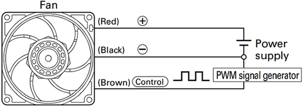
PWM control has the following advantages:
(1) Because the PWM signal is digitally input, precise control is possible.
(2) Because the PWM signal is digitally input, multiple fans can be controlled.
(3) Upon users request, how the fan speed responds to PWM signals can be customized. For example, fan can be set to stop or run at low speed at 0% PWM duty cycle.
2. PWM duty input signals and wiring diagram
Other than a voltage input, an open collector/drain input can be used for PWM signal input.
Using an open-collector or open-drain input may alter the fan’s speed-to-PWM duty cycle characteristics.
Also, applying input voltage or frequency outside the fan’s specified operating range may alter the fan’s speed-to-PWM duty cycle characteristics and result in product breakage.
The input signal voltage and the frequency differ with models. Please contact us for details.

3. PWM duty cycle – Speed characteristics
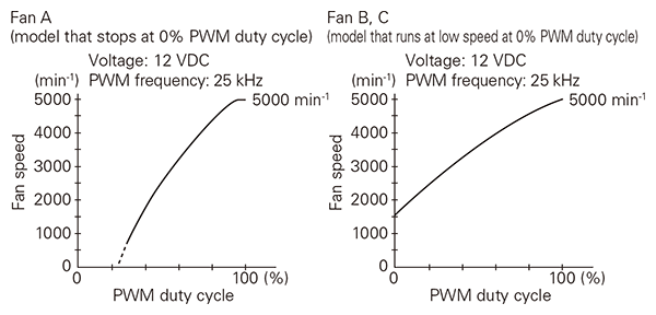
Fan speed of PWM control fans change, as the below performance curve shows, in response to the PWM duty cycle input.
If necessary, users can do the speed setting by themselves, making the fans operate at the optimum speed.
Also, upon user's request, how fan speed responds to a PWM signal can be customized so that the fan stops or runs at low speed for a certain PWM duty cycle input. The below performance curve is for a fan that stops at 0% PWM duty cycle. Specifications differ with models. Please contact us for details.
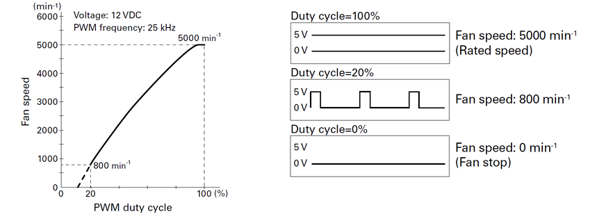
The dotted part of the performance curve (area below 20% PWM duty cycle in the above case) indicates the fan speed is unstable in the area.
4. When you wish to obtain a fan performance with 100 or 0% PWM duty cycle without a PWM signal generator for built-in test.
Performance at 100% PWM duty cycle: Leave the control lead wire open and no connection.*
Performance at 0% PWM duty cycle: Connect the control lead wire directly to ⊖ pin.
* This may vary by model, so see individual product pages for detailed information.
5. Application examples of PWM control fan
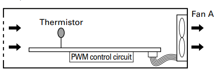
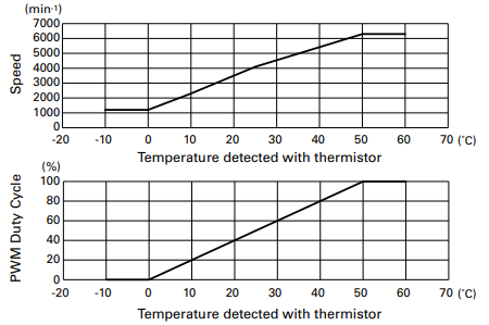
(1) This system controls the fan speed in response to changing device temperature.
By combining a PWM control circuit and thermistor that detects temperature of device and its parts, it is able to control the fan speed of PWM control fan in response to the changing temperature.
(2) Simultaneous control of multiple fans
Because PWM control is done with digital signal inputs, regardless of fan types or input voltage, multiple fans can be controlled simultaneously.
Below figure shows a system that can control multiple fans with various PWM characteristics simultaneously.
Such systems contribute to the low power consumption and noise.
| Operation mode | PWM Duty | Fan A | Fan B, C |
| Full-power | 100% | 5000 min-1 | 5000 min-1 |
| Normal | 60% | 3500 min-1 | 4000 min-1 |
| Standby (eco mode) | 0% | Stop | 1500 min-1 |

San Ace PWM Controller
■Features
Reduces system power consumption and fan noise
For PWM fan speed control, a PWM control circuit needs to be newly designed and configured.
By using this product, however, PWM fans can be fully utilized without the need for preparing new circuits, contributing to reducing the system power consumption and the fan noise.
Can be common-powered by the fan power supply
The controller can be powered by the fan power supply of rated voltage 12, 24, and 48 VDC, and no separate supply is required.
Maximum of four fans connectable
Up to four PWM fans can be connected and controlled.
Please clich Product Sitefor detail.
Last updated: November 2025


